ACROPRINT9200/9250

Rotogravure Printing Machine - Mechanical Line Shaft with Servo Base

Aim Machintechnik Pvt. Ltd.’s varied of converting equipment innovations with a highly graded, designed, accurate, superior finishing, outstanding result with excellence performance and development to achieve high standards in flexible packaging. Its state-of-the-creativity technology offers freedom to carry out convoluted job easily with extraordinary result.

AIM has marketing offices around India and across the world to ensure quickest response time and prompt service to its customers. All activities of the business are focused on delivering Customer Delight and Satisfaction through meeting On Time in Full (OTIF) and Consistent Quality.

Standard Technical Specification

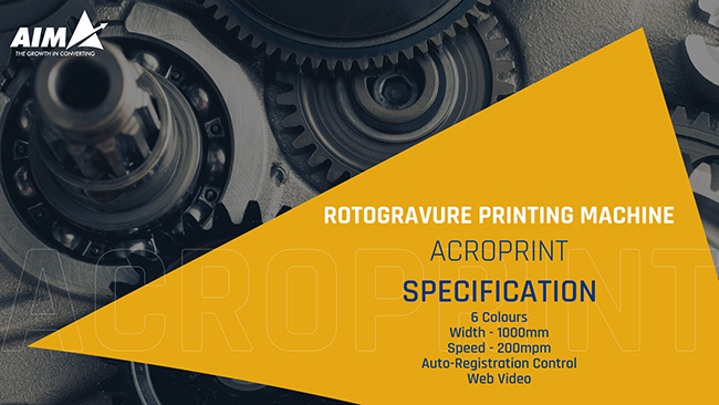
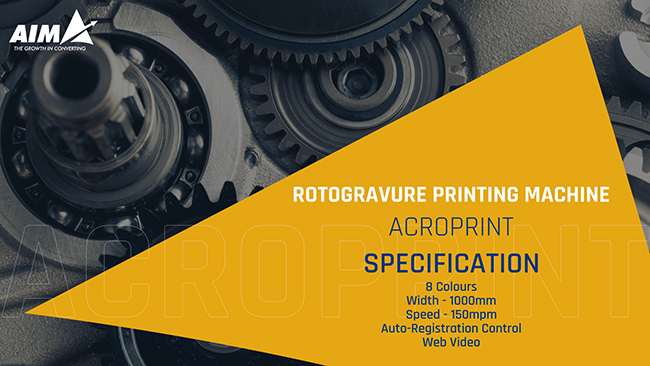
Range of Width 800/ 1000/ 1300(in mm)- As per Requirement
Range of Line Speed(MPM) 200/ 250
Range of Colours 2/ 4/ 6/ 8/ 9/ 10
Printing Repeat Range 400-1200
Web Tension Range 20-400 N
Material’s Range PET, BOPP, LDPE, HM, LLDPE, PP and PVC.

Download Brochure

Quick Inquiry

The Machine

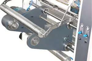
Machine is implemented with German Technology and ergonomically designed mechanical component to deliver optimum performance, superior operational ease, fast registration result response in every high speed, good quality of printing, resulting in higher productivity and reduction in consumption at source, state of the art machine with practically tolerance free format setting ensure reduced film wastage, optimisation of ink solvent and energy consumption, faster job changeover, Programmable AC imported drive driven High Speed Rotogravure printing machine with sturdy design, allow the optimum speed, stability and easy operations.

Distinctively designed accurately & meticulously machined, tough, well built and durable heavy frame structure having good combination of plate with mild steel to maintain accuracy structure mounted on heavy duty base.

Application

The Rotogravure printing machine is very popular and largely used in the photography and fine arts reproduction sectors due to its high density range in printing. The printing process is generally used in packaging sectors and food manufacturing. In addition, it can print a great range of substrates some of which involve polythene, BOPP and polyester among others. The machine is most popular in this sector due to its capability to print fine on thin films like nylon and polyester. Also, the printing process is applied in manufacture of transfer printing and wall covers.

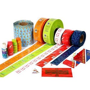
With the Finished good like Namkeen Pouch, Rice Bags, Aluminium Pouch, Cement bag, Non woven rolls, PVC Shrink Labels, sack film, Cereal packaging, Courier bags / security bags, Surface protection film, Compression packaging pouch and Laminated Pouch Packaging film Products.

Machine Layout

Fully Automatic Rotogravure Printing Machine

Salient Features

All the control panel of printing stations mainly substitute of electronic and pneumatic.

  • Electronic Substitutions
    • Emergence Stop
    • Air temperature controller/indicator for drying chamber
    • DOL (Department of Labour): Necessary protection and fault indicator
    • Joy Stick for manual length and registration setting
    • Push button for blower and drying system
    • Printing colour Sensor for Automatic registration control
  • Pneumatics Substitution
    • Pneumatic controls, pressure gauge and regulator for Impression rubber roll and doctor blade
  • Automatic registration control system uses superior technology, which enables more accuracy, efficiency and productivity
  • ARC is a registration controller designed in order to obtain maximum operation flexibility combined with best reduction in west
  • Automatic length & side-lay registration control system with full coloured touch screen operation interface facilities automatic mark centring and recognition
  • Automatic selection of different control parameters during machine speed changes and control parameter individually configurable to different materials for easy operator selection
  • FIBER OPTIC COLOUR SCANNING HEAD: For communication is faster so can result in high measurement accuracy and registration stability and colour mark display for better visualization
  • Standard and Turret type unwinder is facilitated

Standard

  • Facilitated with Web guiding system
  • Adjustment of 3” and 6” core for shaft-less on unwind and rewind
  • Sleeve chuck is provided in shafted unwinder
  • Gear shafted is also available
  • Unwinder web handling control using the latest generation AC servo technology
  • System mainly composed of AC servo motor and drive, pneumatically loaded low friction dancing roller assembly ad load cell for tension feed-back and actual tension display
  • Electro-electric Edge guiding system equipped with ultrasonic edge sensor
  • Hard Chromium Plated Steel Roller is provided
  • The Infeed nip unit drive pulls the substrate off the unwinding roll, and simultaneously ensures that tension in the span between the Infeed section and the first printing station is maintained constant
  • It maintains set tension independent of whether it is called to drive or to prevent overhauling. An AC or DC motor actuates the Infeed nip through an appropriate mechanical transmission arrangement. Tension transducers or dancer position sensors are used for feedback.
  • Speed-follow-tension-trim (or dancer-trim) controls along with vector-controlled digital AC drive or digital DC drive ensures that process tension is maintained constant
  • AC Frequency drive based on automatic direct web tension using 5 drive system
  • 5 Drive system as unwinder, rewinder, common for all print units, infeed & outfeed are individually driven by servo motor drives controlled & supervised by the high performance controller having its own intelligent software
  • To providing fast, reliable & jitter-free communication using al drives as
  • Ethernet/ IP Based Communication system’ to maintain tight synchronization
  • Operator control panel mainly consists of touch screen operator interface located at rewind side facilitated easy operation
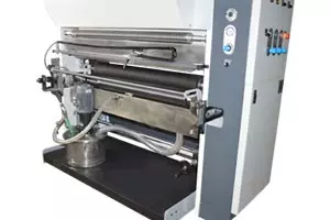
  • For quick change of engraved cylinder and the whole inking group facilitates fast and easy changes
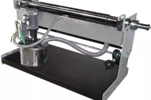
  • Trolley consists of hollow type cylinder mounting shaft assembly with quick locking check nut, double ink-basin and variable speed AC Motorized Ink Pump
  • New design ink tray with ink delivery nozzle to reduce ink foaming and better disbursement of ink
  • The inking system has been designed for consistent and uniform inking at high speed, as well as low volume of ink consumption in circulation throughout the printing
  • The new design of splash guard to reduce ink splashing
  • The impression roller is a steel tube covered by an elastic polymer, such as natural rubber, or synthetic rubbers
  • It is driven by frictional forces generated by contact with the motor-driven gravure cylinder
  • The impression roller is usually smaller than the gravure cylinder, and consequently runs at a higher RPM than the gravure cylinder

SLEEVE TYPE IMPRESSION ASSEMBLY (OPTIONAL)

  • The sleeve system, consist of an air mandrel with a rubber covered fibreglass sleeve, provided functional flexibility and sleeve change without tools
  • Sleeve type rubber covered impression roller raising-lowering on precision linear bearings
  • The precision linear bearing ensures smooth and precise displacement
  • Main machine control is programmable for automatic detach of the pressure roller at machine stop
  • Pressure roller sleeve with antistatic rubber, solvent resistant made of fibreglass
  • Important process variables in gravure coating & printing are the rotational position at which the blade wipes the cylinder; the angle that the blade makes with the tangent to the cylinder at the contact point; and the pressure applied to the blade
  • Designed to ensure a straight profile of the blade resulting in lesser blade pressure, better printing quality and longer cylinder life
  • Eccentric rod without tools for blade locking
  • Group sliding with low friction bearing reciprocating transversal movement of the doctor blade is taken from the reduction gearbox of the main line shaft
  • On the engraved cylinder doctor blade position group allows horizontal and regular adjustment
  • Pneumatic doctoring pressure with adjustment possibility from the unit control panel
  • Fine adjustment of in-and-out position, independently on left and right, must also be possible, in order to compensate for any misalignment between blade geometry and cylinder axis
  • These requirements are fulfilled by a doctor blade assembly which includes a doctor blade holder
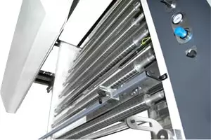
  • Ink drying is obtained by blowing hot air on the web through air nozzles
  • Pneumatic operated Separate dryer on each station consists of digital temperature controller
  • Air Nozzle, blowing air on the web in connection with the idle rollers, to ensure the proper drying, avoiding shaking or deforming of the web itself

High Efficient Ventilation Section

  • In high ventilation section ensuring optimum drying at minimum energy consumption
  • For good enough to send and r-circulate air common ventilation section for all printing station
  • Connection ducts and exhaust silicon pipes fir the delivery and re-circulation between the drying chamber and the ventilation section
  • Manually operated restraint used for adjustment of air balancing
  • In ventilation section composed of the centrifugal blower with AC motor, thermal oil or electric heat exchanger, other necessary controls and feedback device for temperature
  • High Capacity Heating System, Fully automatic unit – Maintains the desired temperature of the thermic fluid, High System Efficiency – Reduced operating cost, Best applicable for High-Temperature Heating and Minimum site work and ease of installation
  • Thermic Fluid heating system (instead of electrical heating system)- The System consist of temperature control on/off valve, Globe valve, Pressure gauge, Piping within the machine area, Fitting, etc. For thermic fluid heating system
  • Web material transported within converting machines will not always track straight. A web guiding system is required for proper alignment of the material
  • A variety of factors such as, poor quality raw materials, material property variations in raw materials, improper machine alignment, improperly maintained machines, environmental conditions, and processing conditions, cause lateral web misalignment as they are transported in the converting machines/lines
  • Lateral variations due to poor quality of raw material include telescoped rolls, poorly wound rolls with lateral misalignment (see image below), cambered webs, raw material with web thickness variations, etc
  • Even if the raw materials are perfect, process variations in speed and tension might cause changes in traction that steer the web improperly. Finally, roller misalignment, changes in roller drag and air entrainment between the web and roller can cause lateral misalignment
  • The system provides precise tension control of the web before entering to the first printing station and isolates the printing unit from tension disturbance of the unwinding zone
  • Dancing roller on pivoting lever mounting loaded by a counterweight (unique mechanism for tension feedback) having motorized movement by means of slo-syn motor. The dancing roller position controls the speed of the in-feed motor
  • Specially designed, dynamically low friction-low inertia idle rollers made of aluminium ally mounted on-low friction bearing, enhance rotational smoothness
  • Metallurgy, shaft end, internal boring of the aluminium pipe is done, computerized dynamically balancing, bearing with self lubricate and temp resist grease
  • The Optical colour sensor on individual stations detects the mark continuously when the machine is running and speedily calculates the registration error and conveys it to the control unit
  • The control unit generates necessary motor control output in order to correct error. The system will control registration error, independent of machine speed
  • Automatic Mark Search - Gate can set automatically by clicking on the Auto search. It automatically puts the gate according to selected master slaves to save the time
  • Motorized web video inspection system consists of high quality CCD colour camera, industrial pc & monitor
  • Synchronized System – It helps to register printing to up-down and right left adjustment as manual and it is help ARC for adjust printing as command of ARC
  • Transmission - Power transmission from main common motor to all the printing units is done mechanical line shaft with help of gear box to the cylinder by manual coupling joint
  • Out-feed system pulls the substrate from last printing unit
  • The system provides precise tension control of the web before entering to the rewinder and isolates the rewinder from tension disturbance of the printing unit
  • The system mainly composed of matt chromium plated steel roller AC servo motor and drive, load cells and rubber covered nip roller with pneumatically adjustable pressure
Close